Reproduction and Application of Traditional Chinese Timber Structure Components
Adviser- Yang Ting Shen, 蔡侑樺
Student- 黃廉凱
Date- Jul 2023
Methodology of reproduction
Background
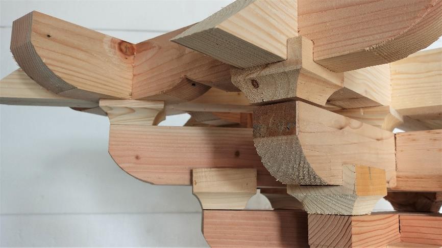
In Chinese traditional timber construction, “Tou-Kung” is one of the distinctive components. Bracket serves as a structural element that supports the massive roof, resulting in an elegant curve on the facade. The essential details of Chinese traditional timber construction are recorded in ancient Chinese lang uage books and presented through hand drawn illustrations in works such as ” Ying-Zao-Fa-Shi (李誡, 1103) and ” Ying-Zao-Fa Yuan (姚承祖, 1986) . In the past, the production of bracket relied on the craftsmanship of artisans.
The fabrication of bracket components required meticulous refinement and precise assembly of various parts, which consumed a significant amount of time. The production process relied not only on the skills of the artisans but also on their logical understanding. With the rapid development of digital parameter tools such as Building Information Modelling (BIM), the idea of applying BIM for the “digitalization” of traditional architecture has become feasible. One of the earliest examples of applying parametric design in ancient Chinese architecture demonstrates that bracket is a key module of the entire structure. structure.(Yang-Ting Shen, 2022; Zhao et al., 2021)
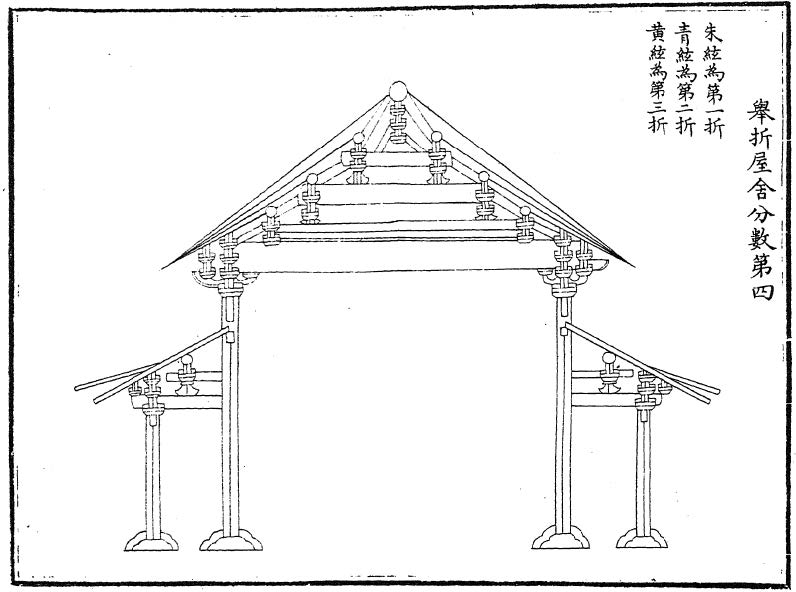
Figure4-1 One of the traditional Chinese timber
construction methods recorded in the Ying-Zao-Fa-Shi
Source: Li Jie, (李誡, 1103)
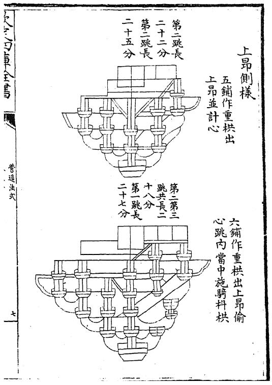
Figure 4-2 The Ying-Zao-Fa-Shi documents various construction methods of bracket sets.
Source: Li Jie, (李誡, 1103)
The research on bracket sets is distributed across multiple countries, such as Taiwan, Japan, Korea, and China, where these structures have been adopted in their ancient buildings or temples. Several studies have demonstrated that digital fabrication using CNC machines can replicate a significant portion of traditional bracket joint components. Takabayashi successfully reproduced traditional Japanese timber joint components using a CNC machine equipped with various tools such as circular saws, jigsaws, and reciprocating saws. (Takabayashi et al., 2018; Yang-Ting Shen, 2022)
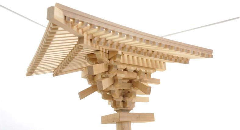
Figure 4-3 Takabayashi utilized CNC technology to fabricate the Roof Corner of the Five Storied Pagoda
in the Japanese Traditional Timber Structure.
Source: H. Takabayashi, 201 9 (Takabayashi et al., 2018)
Zhao, on the other hand, focuses on optimizing the structural behavior of bracket sets using parametric tools for manufacturing with a robotic system.(Zhao et al., 2021) Most of these studies mention that one of the key factors in replicating bracket set structures relies on the “correct” and “precise” digital models, which provide comprehensive manufacturing information. Therefore, the digitization of bracket sets for the intervention of digital fabrication tools becomes a critical task in this research.(Yang-Ting Shen, 2022)
Method
This study selected the “corner set” (轉角鋪作) from the Nan Chan Temple in Mount Wutai as the prototype for reproducing the traditional Chinese timber structure known as “five bracketing with double eaves and overlapping rafters” (五鋪作雙杪偷心造). The chosen structure comprises the roof support system and the columns 金柱 representing a typical combination in Chinese traditional timber construction. In this chapter, we present an integrated workflow based on Building Information Modeling (BIM) and robot based manufacturing for the preservation and reproduction of bracket craftsmanship. The experiment aims to achieve the following three objectives:
(1) Digitally preserve the “form” and “relationship” characteristics of the bracket.
The bracket is a general term for Chinese traditional timber construction, encompassing several different structural typologies. Therefore, it is essential to identify the specific typology or characteristics of the components through literature or existing structures. Subsequently, parameter descriptions can be developed based on these identified features for the purpose of digital preservation.
(2) Perform assembly and machining simulations using the digital twin model.
Before actual manufacturing takes place, all demonstrations must be achieved through a “virtual” model. Therefore, the concept of digital twinning is crucial. Whether it is assembly testing, selection of processing methods, actual processing conditions, or real world environmental parameters, they all require the assistance of the digital twin model to enable proactive assessment of potential events and the formulation of corresponding strategies to avoid unforeseen circumstances.
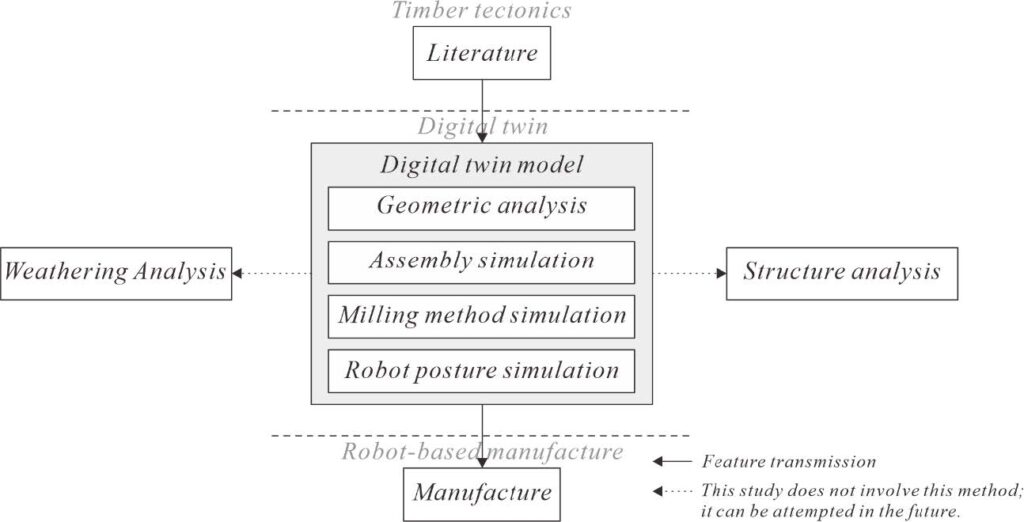
Figure 4-4 Explanation of the simulation items included in the digital twin and their hierarchical relationships.
Source: This figure was illustrated by the author.
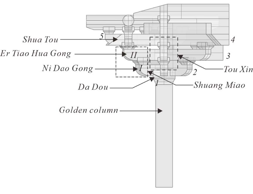
Figure 4-5 Explanation of the features and components of the ” Wu Pu Zuo Shuang Miao Tou Xin Zao ” (五鋪作雙杪偷心造):
1) Numerals: Refers to the types of brackets used.
2) Shuang Miao Position: Indicates the Roman numeral of bracket extensions from the column
3)Tou Xin Position
Source: This figure was illustrated by the author.
(3) Reproduce all components of the bracket through digital manufacturing and
complete the assembly process.
The main reason for choosing robot based manufacturing in this study is that traditional Chinese timber structures exhibit a significant characteristic of complex and relatively unique components, with a limited number of repetitive elements. Therefore, the customization aspect becomes crucial for their reproduction. Robot based manufacturing offers the advantage of meeting this requirement, making it an appropriate choice for assisting in the fabrication of the majority of the components in the timber structure.
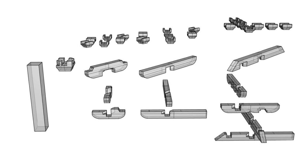
Figure 4-6 Schematic diagram of the bracket components in the ” zhuan jiao pu zuo” of this study.
Source: This figure was illustrated by the aauthor.
We begin the entire workflow by establishing a BIM bracket model based on literature. This model includes both geometric and non geometric data. The geometric data provide relevant descriptions of the overall shapes of bracket components, while the non geometric data describes the assembly relationships among various components, such as the logical connections and assembly sequence of the components, such as the ” Tou” and “Kung.” Subsequently, based on the BIM database, we plan the manufacturing information for the robot, allowing the robot arm to reproduce the bracket components in the style of Nan Chan Temple.
Robot base manufacturing environment and tools
Processing environment
The robotic manufacturing setup consists of the following components:
- Industrial robot: KUKA KR300 industrial robot equipped with a woodworking spindle, featuring a seventh axis movable track.
- Clamps: A pair of pneumatic clamps used to prevent wood movement during milling operations.
- Dust protection enclosure: Several dust protection shields made of glass and plywood surround the machining area, preventing dust dispersion in the workspace, ensuring operator safety, and enabling real time monitoring of the milling process.
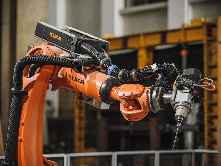
Figure 4-7 KUKA KR300 with Woodworking Spindle.
Source: RAC Coon, 2023
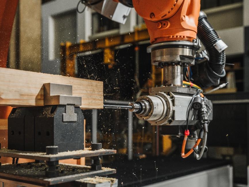
Figure 4-8 Pneumatic Clamps on the Machining Platform.
Source: RAC Coon, 2023
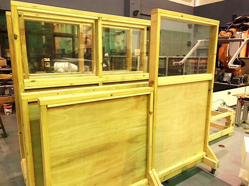
Figure 4-9 Dust Protection Enclosure composed of 5mm tempered glass and 18mm plywood.
Source: This image was captured by the author.
Tools
To accommodate the wood spindle, the experiment utilized the following tools for various machining purposes.
- Positioning drill bit: A tool used for environmental parameter positioning before milling.
- End mill: A tool used for adaptive method and pocket method cutting.
- Ball end mill: A tool used for contour machining.
- Face mill: A tool used for large area milling and surface levelling.
- Circular saw: A tool used for cutting or slotting operations.
Record of the experiment procedure
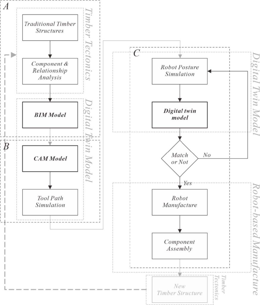
Figure 4-10 The experiments in this chapter are mainly divided into three major parts:
A) Digitalization, B) Digital twin, and C) Robot base Manufacture.
By integrating the se three parts, the research aims to establish a comprehensive workflow for the reproduction and preservation of traditional timber structures using digital technologies.
Preserving bracket craftsmanship through digitalization
The preservation of the “form” aspect of bracket craftsmanship is achieved through the application of Building Information Modelling (BIM) technology. The following steps outline the process (Yang-Ting Shen, 2022):
Part A
- Data Acquisition:
Collect comprehensive literature and documentation to record the geometrical and non geometrical data associated with bracket craftsmanship. - Adaptive Com ponent Modelling:
The adaptive component modelling technique is employed to create various components of the bracket. This approach allows nodes to be associated with boundary data, ensuring flexibility and adaptability during the innovation process. Therefore, automated component adaptation is of great importance since Chinese traditional timber construction component relies on proportion, and there are specific rules governing the proportions between different elements. The width of a column, for example, w ill influence the dimensions of all subsequent components. Thus, to preserve the character of “proportion,” the involvement of adaptive components becomes necessary, thereby achieving the reproduction of components while maintaining this characteristic feature. - Sorting and Labelling:
Organize and label the bracket components based on their respective types and assembly sequences. This systematic approach facilitates efficient organization and accurate representation during the subsequent stages. - Integration into the BIM Model:
Incorporate the created bracket components into a BIM model. This integration process entails utilizing the collected data to accurately represent the digital model of the bracket structure. - BIM Component Library:
Establish a dedicated BIM component library specifically for bracket components. This library enables easy access to component data from existing timber structures, allowing for parameter adjustments to meet various dimensional requirements. - Spatial Documentation:
Document essential information within the BIM model, including component names, 3D shapes, categories, materials, and assembly sequences. This documentation serves as the basis for generating manufacturing instructions and further fabrication information.
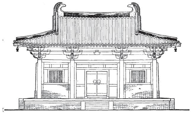
Figure 4-11 This is a caption for the literature referenced during the data collection process for the redrawing of Nan Chan temple main hall.
Source: (建筑史学刊, 2022)
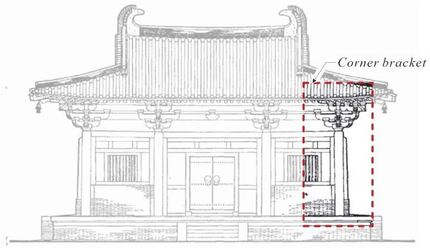
Figure 4-12 After analysis, the corner bracket is selected as the target for this reproduction.
Source: This image was captured by the author , background (建筑史学刊, 2022)
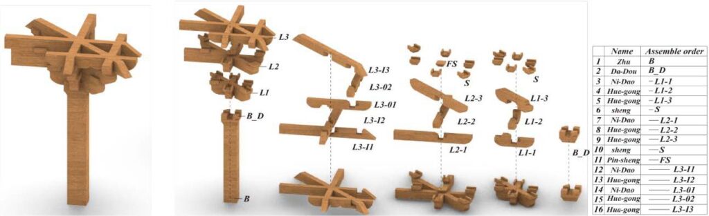
Figure 4-13 Bracket is a timber construction method that emphasizes the assembly sequence.
Source: (Yang-Ting Shen, 2022)
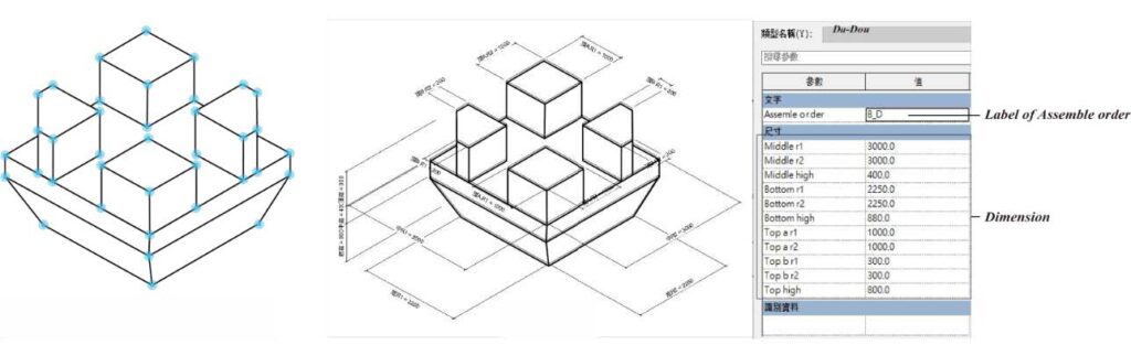
Figure 4 14 Adaptive components facilitate proportional or dimensional adjustments within the identical “type” of bracket.
Source: (Yang-Ting Shen, 2022)
By leveraging BIM technology in the preservation process, the “form” aspect of bracket craftsmanship can be effectively protected, opening up new possibilities for conservation efforts and future applications.
Reproducing bracket components through digital fabrication
Digital manufacturing technology plays a crucial role in the preservation and replication of bracket components. This section outlines the step by step process of replicating bracket components using digital fabrication methods.
Part B
- Conversion from BIM model to CAM data:
Import the Building Information Model (BIM) into Computer Aided Manufacturing (CAM) data format. Convert the BIM model into a format suitable for the digital manufacturing workflow. - Analysis of bracket component geometry composition:
Perform a detailed analysis of the geometric composition of each bracket component. Identify the unique geometric features and structural composition of the components. - Decomposing components for fabrication:
Decomposing the bracket components into individual fabrication parts based on their geometric composition. Determine the appropriate fabrication methods for each part.
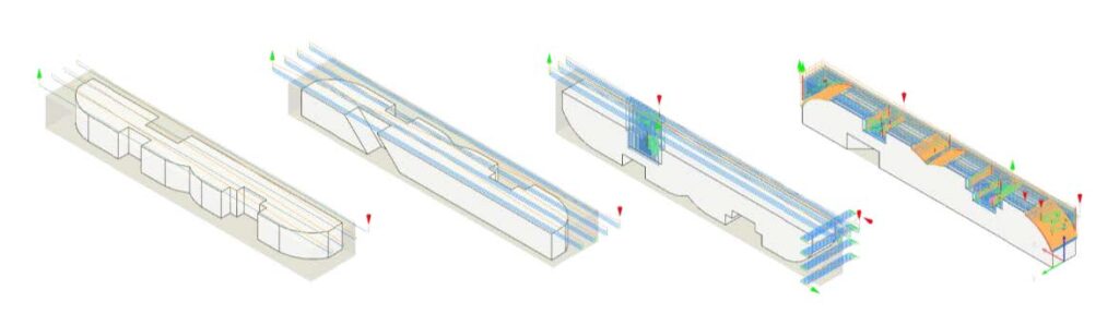
Figure 4-15 Selected Machining Methods and Tools for Constructing Various Bracket Components through Geometric Analysis: A Case Study of the “kung”.
Source: This figure was illustrated by the author.
Demonstration of workflow using “Da-Tou ” component (Yang Ting Shen, 2022) 2022) (refer to Figure 4-16):
- Analysis of “Da-Tou” component geometry:
Analyze the geometric shape of the “Da-Tou” component and divide it into three parts: surface part, sink part, and slope part. - Selection of machining tools:
Choose appropriate milling tools for the manufacturing process. - Specification of tool sequence:
(1) Face milling cutter for surface flattening.
(2) End milling cutter for rough sinking.
(3) Ball nose cutter for milling curved slopes and surface polishing. - Consideration of f lipping process:
Consider the multi sided geometry of certain parts that require flipping during the manufacturing process. Ensure comprehensive machining and surface quality for all parts.
The above step by step process demonstrates how digital fabrication technology is applied to replicate bracket components with precision and high quality. By converting the BIM model to CAM data, analyzing the geometric composition, disassembling the components, and following specific machining workflows, digital manufacturing enables efficient replication of bracket components with accuracy and reliability. (Yang Ting Shen, 2022)
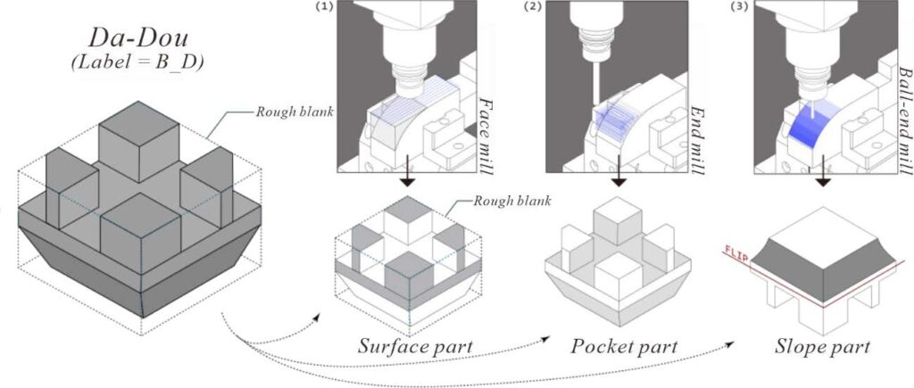
Figure 4-16 Determining the selection of machining tools through geometric analysis.
Source: (Yang Ting Shen, 2022)
The entire fabrication process can be easily replicated using common software in the CNC machining field. The complete workflow of Tou-Kung reproduction consists of three main stages (Yang Ting Shen, 2022) (refer to Figure 4-17)
Part C
- CAM planning:
Import the BIM model into Autodesk Fusion 360, generate tool paths, and export them as XML files. - Robotic arm planning:
Transfer the XML files to KUKA | prc in Grasshopper, set up the orientation of the fabrication coordinates, and specify other robotic manufacturing parameters. Simulate the entire robot movement process to check for potential collisions or singularities an d ensure safe and efficient fabrication. - Fabrication execution:
During each fabrication stage, materials may need to be flipped for multi sided processing. After locating the materials, convert the work paths into robot commands and execute them using the robot teach pendant to replicate the Tou-Kung components.
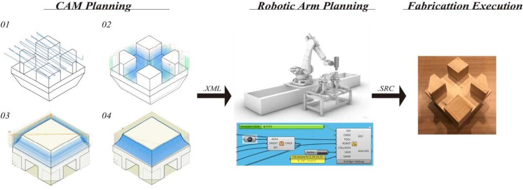
Figure 4-17 The complete workflow of bracket reproduction consists of three main stages.
Source: (Yang-Ting Shen, 2022)
Summary
This research applied this workflow in the robotics laboratory to replicate the bracket of Nan Chan Temple. Ultimately, we completed 27 components and assembled them into a complete bracket structure. In comparison to artisanal craftsmanship, several issues can be discussed:
Manufacturing aspect: The entire manufacturing process took approximately 52 hours, which, according to interviews, is about three times faster than manual craftsmanship.(Yang Ting Shen, 2022)
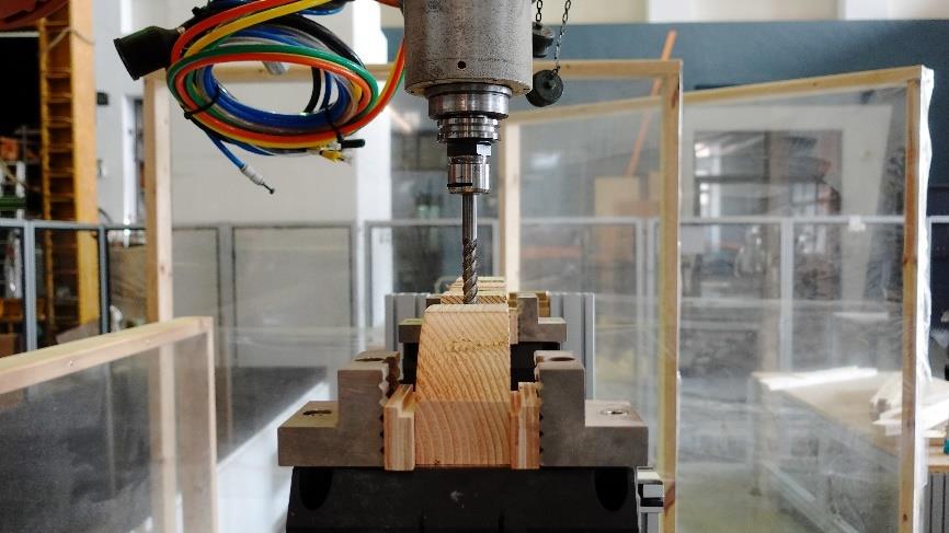
Figure 4-18 The utilization of CNC combined with a six axis robotic arm for milling the bracket components can significantly reduce the material removal time.
Source: This image was captured by the author.(Yang-Ting Shen, 2022)
Accuracy aspect: The dimensional tolerance of t he prototype was less than 0.5mm, demonstrating high precision, but further improvements are still required.
Discussions with heritage conservators and cultural experts raised some concerns and considerations. The machining of components may need refinement to meet the quality requirements for smoothness and glossiness during finishing. (Yang-Ting Shen, 2022)
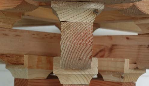
Figure 4-19 Under CNC machining, high accuracy in real world coordinates is crucial. Therefore, even
minor deviations in the clamp can result in non right angles in the final component.
Innovation and current limitations: The framework is still in the development stage, and future research will address current limitations such as achieving a unique handmade feel, improving the smoothness of finishing, and differentiating it from bracket crafted by artisans. Additionally, applying it to cultural heritage restoration may pose some challenges. These limitations necessitate further experimentation and communication with heritage conservators and cultural experts to understand their requirements. Furthermore, we anticipate applying more traditional timber structural components, and in the future, we will develop additional tools and manufacturing methods to address more complex geometric shapes. (Yang Ting Shen, 2022)
Figure 4-20 The final finished surface of mechanical milling exhibits varying degrees of roughness due to different parameters and wood species. However, regardless of the parameters used, there is still a noticeable gap compared to the smoothness achieved by artisanal hand planning.
Source: (Yang Ting Shen, 2022)
Therefore, in this experimental process, it can be observed that even with CNC control, while achieving high precision is possible, due to the characteristics of milling and the nature of wood, path traces are easily left on the workpiece. To obtain a smooth surface, a secondary finishing process is necessary. However, this secondary process involves not only sanding off the path traces but also achieving a glossy finish. Hence, solely relying on robotic arm machining cannot meet the standards of heritage restoration. The collaboration between robotic arms and craftsmen is essential to achieve the restoration criteria.