Trail Pioneering Project of Digital Twins Tectonics
NCKU | Dept. of Arch | RAC-Coon | RATs | 2023
Advisor– Shen, Yang-Ting Yen, Chia-Ching
TA– Huang, Chu- Hua Huang, Lien-Kai Gao, You-Min
Designer- Ho, Pei-En Hung, Huai-Yun Tsao, Yung-Hsing, Pan, Zhong-Yu Liao, Chen-Chia Tai, Huai-An
Site
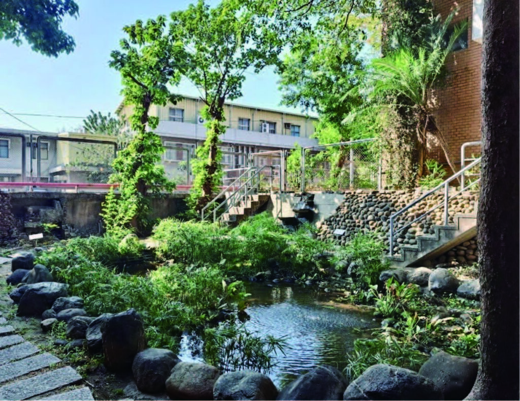
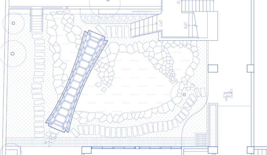
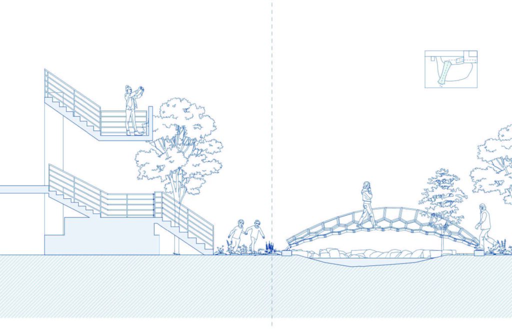
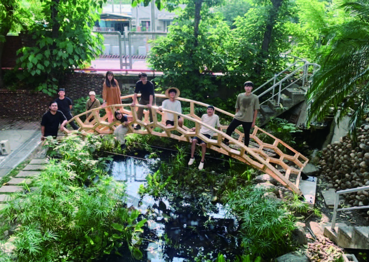
The designated site for this project is a constructed wetland located between the buildings of the Department of Architecture at National Cheng Kung University.
This ecological artificial wetland, designed by Professor Lin Hsien-Te of the Department of Architecture, serves as a green space situated between the two main buildings. On its left and right sides, it connects the student studios and the architectural service core.
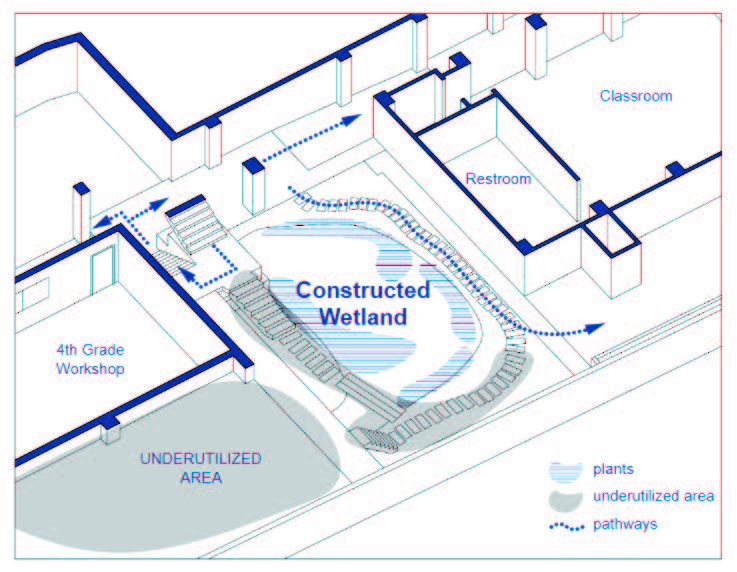
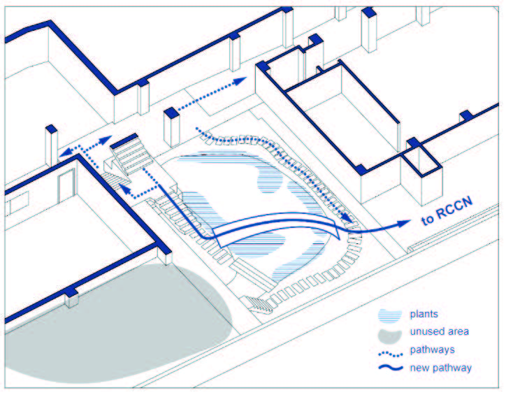
Regarding the current condition of the site, there are several underutilized grey areas that have not been fully utilized. The usage of existing pathways is relatively low, and these fragmented grey areas restrict the available space for any structure on the site. Furthermore, the most distinctive feature of the ecological pond lies in the abundant planting of tall aquatic vegetation, creating a diverse and lush appearance within the ecosystem pond.
Design process
BRIDGE IMAGE
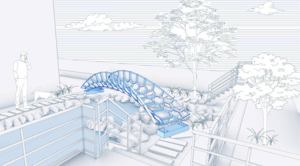
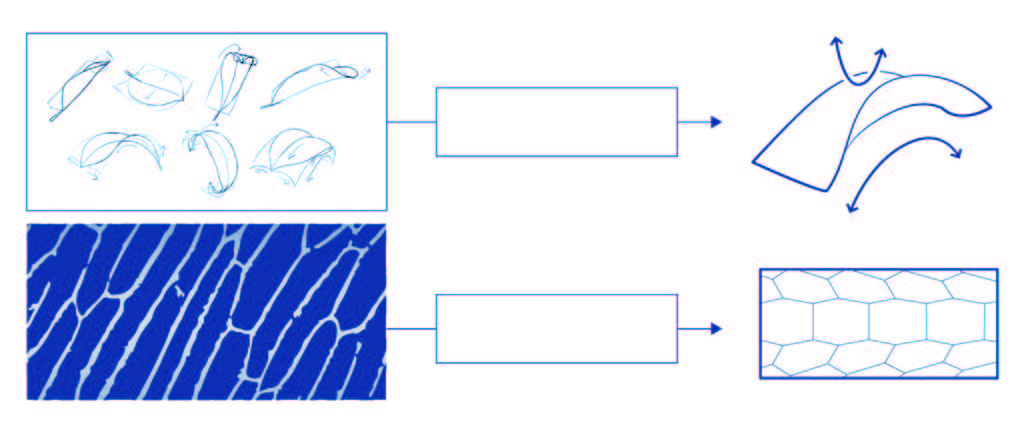
The concept was inspired by the natural textures of the constructed wetland, taking the imagery of falling leaves as its starting point. It evolved into the most primitive form of a hyperbolic paraboloid shape. The patterns on the curved surface were derived from the cellular structure, where hexagonal geometric
shapes were parametrically designed and applied to the surface. This artwork embodies the essence of “Veins of Fallen Leaves.”
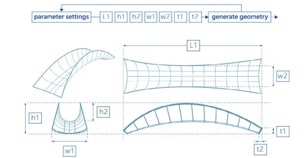
FORM GENERATION
During the form-generating process, we opted for Rhinoceros Grasshopper as a parametric design tool to generate our bridge. Through digital assistance, we input given variable parameters, namely L1, h1, h2, w1, w2, t1, and t2, to control the bridge’s length, height, width, and curvature. By leveraging computer calculations, we achieve the final outcome, allowing for flexible adjustments of the design to suit the site or specific requirements.
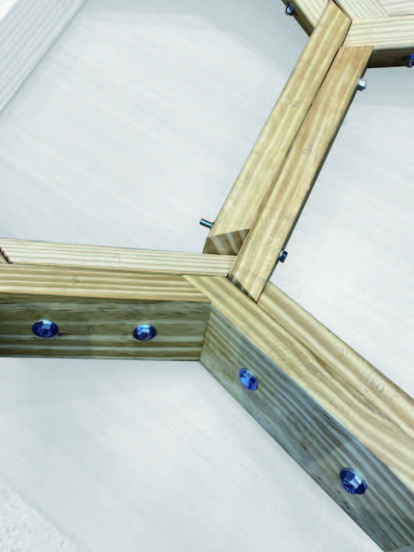
Tectonics
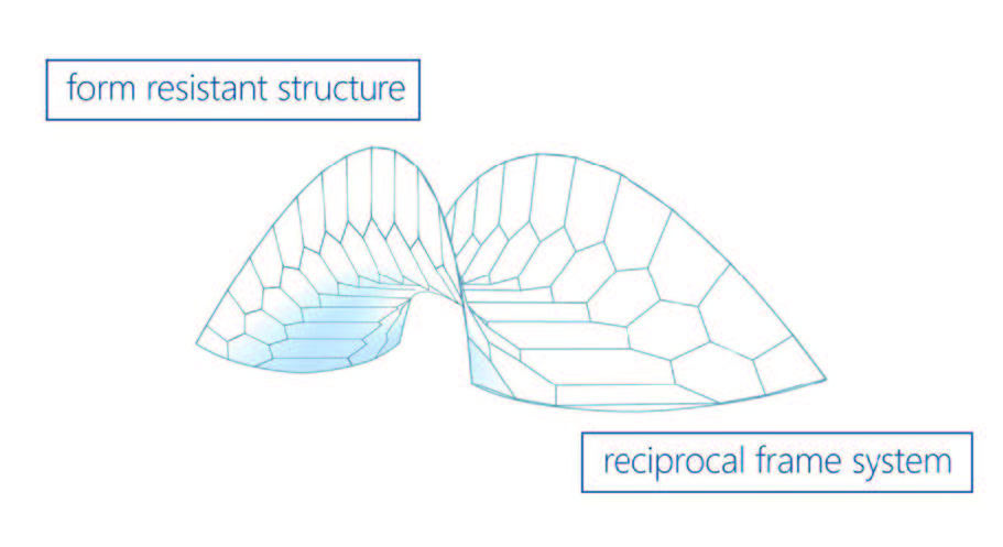
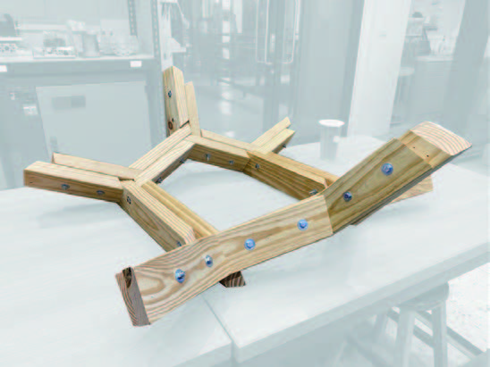
In simple terms, the final design outcome is a composite structure composed of hexagonal patterns applied to a hyperbolic paraboloid surface. It inherits the inherent form-resistant characteristics of the hyperbolic paraboloid, remaining a non-developable surface when rigidly connected, providing structural stability.
Furthermore, we contemplated the appropriate detailing and joining methods to imbue it with a reciprocal frame system’s structural behavior. By utilizing the interaction forces between each unit, we aimed to enhance the overall stabilityof the bridge.
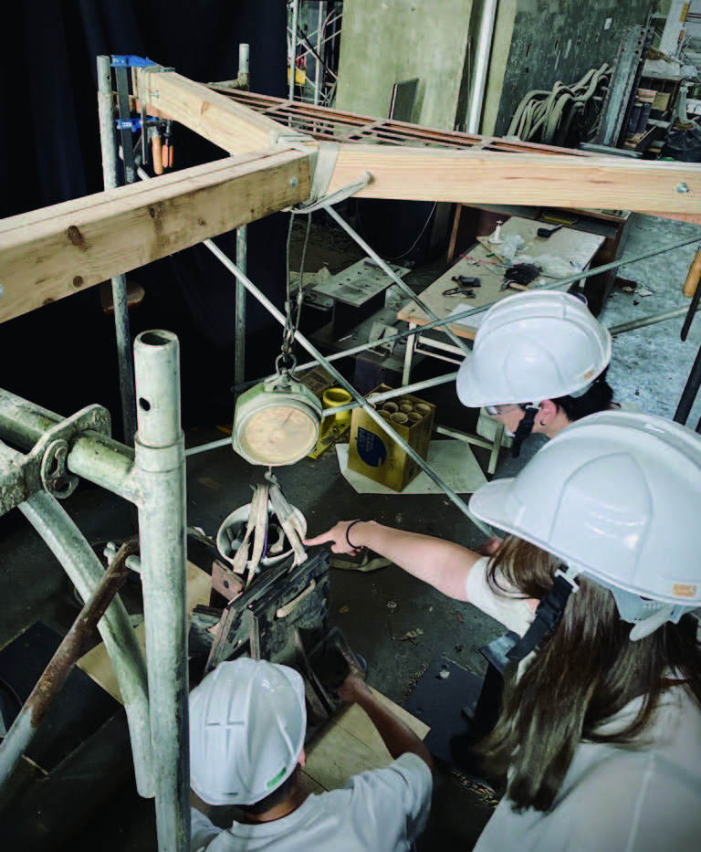
Max. Bending Moment : 1300 kg-cm
Required Load Bearing : 80 kg
Safety Factor : 0.5
Final Load:150 kg (deformation 5cm)
Then we decided to conduct specific structural tests on the jointing units. The objective is to calculate the overall bridge’s load-bearing capacity based on the behavior of individual joints, thus reviewing and ensuring the bridge’s stability.
Parameters
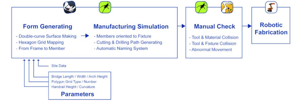
The entire parametric design process is divided into three major parts. The first part involves the generation of the bridge structure’s design. The second part entails simulating the manufacturing process. The third part involves manual adjustments before finally proceeding to the stage of robotic arm fabrication.
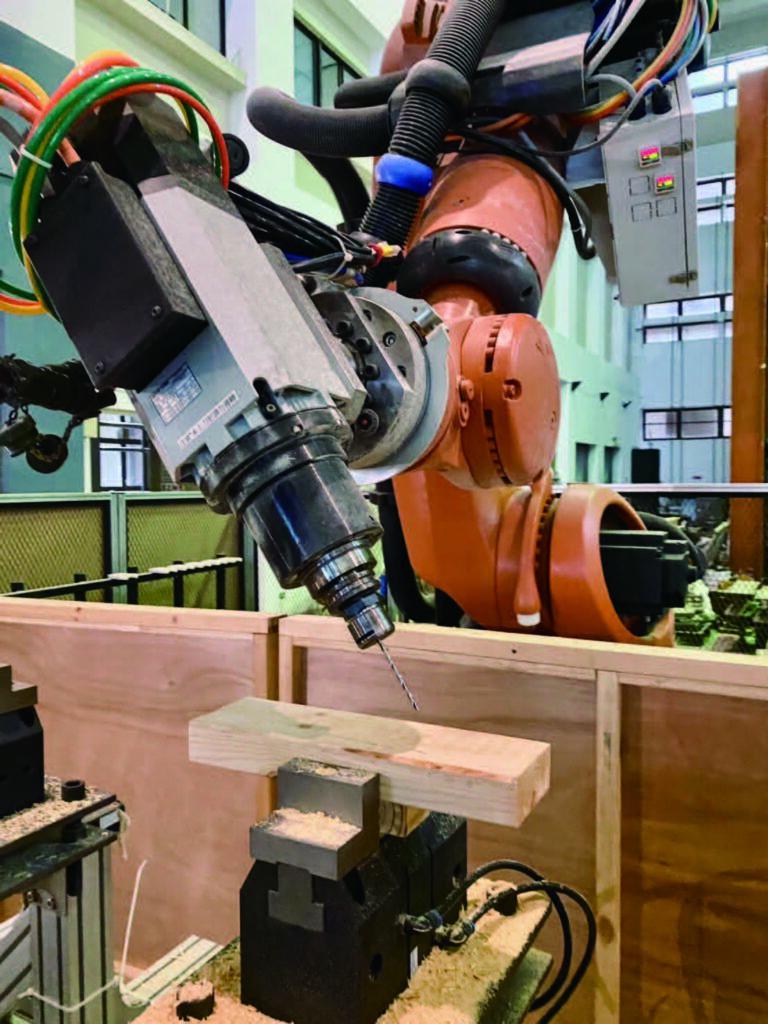
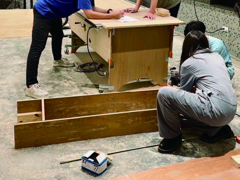
Fabrication
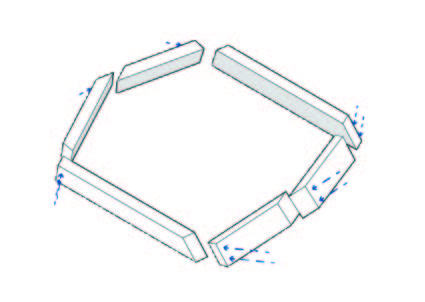
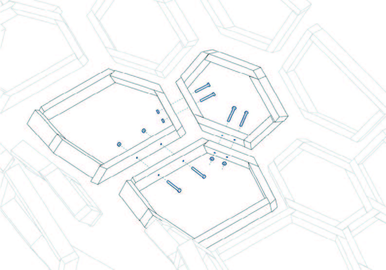
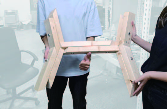
Members to Units
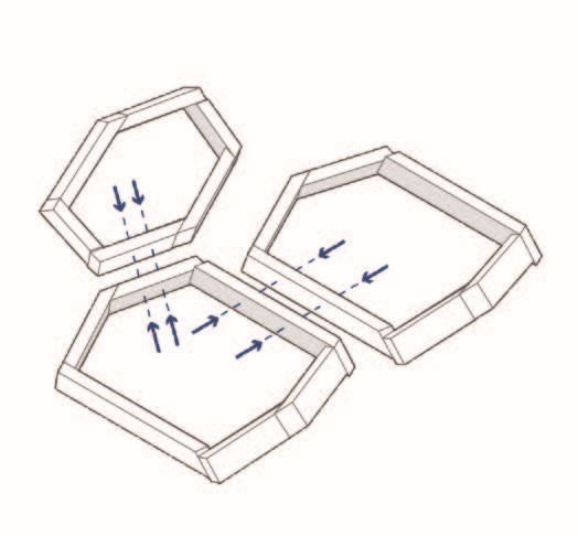
Units to Clusters
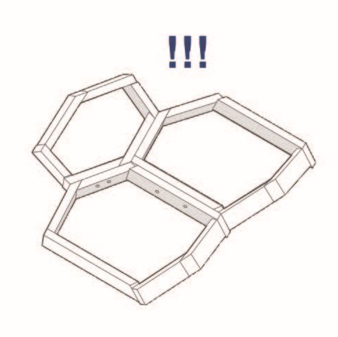
Clusters to the whole
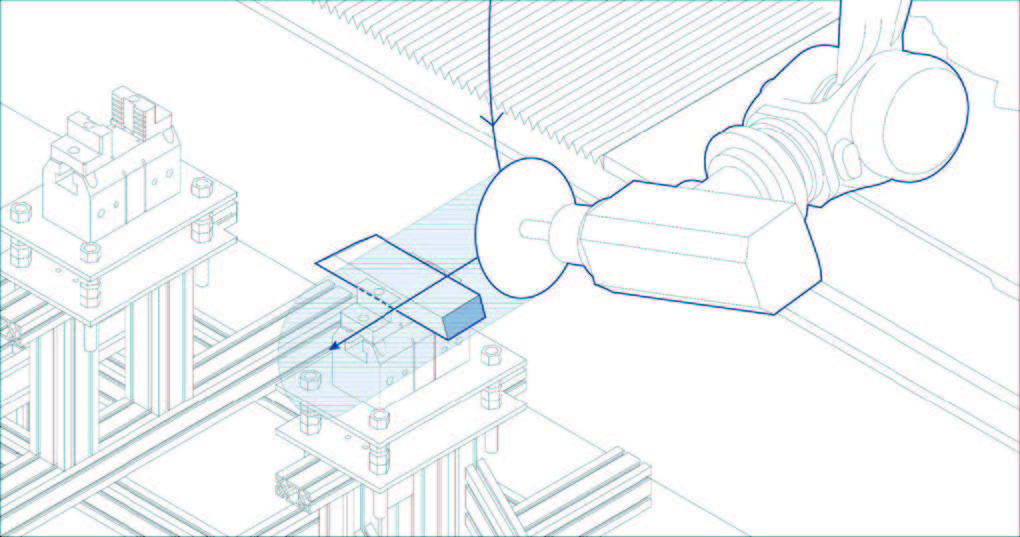
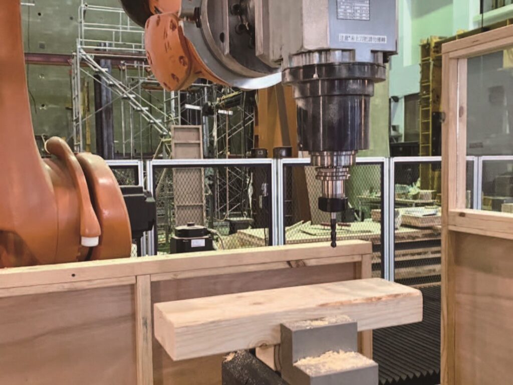
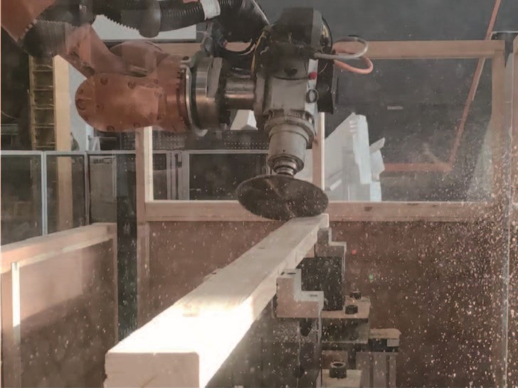
Step 01.
CIRCULAR SAW CUTTING
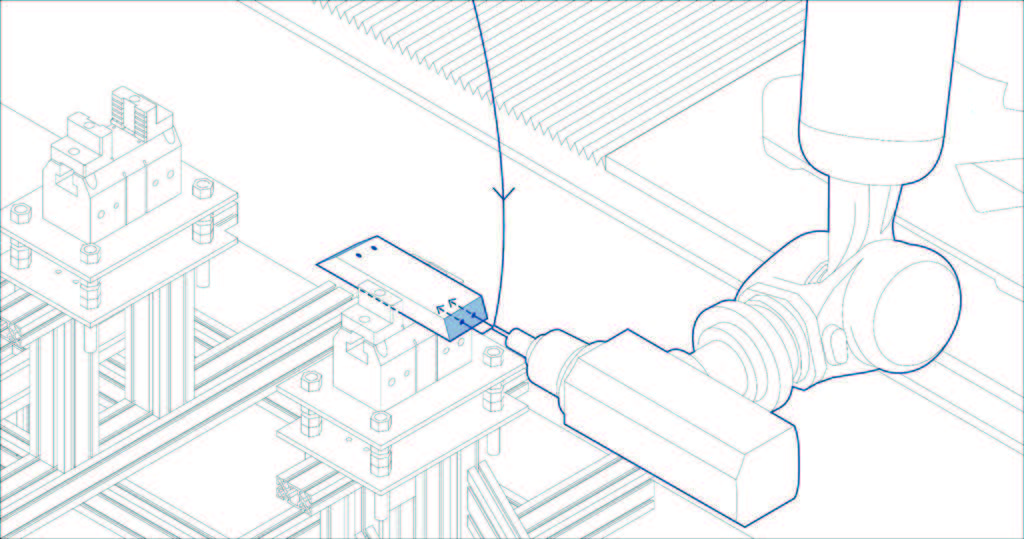
Step 02.
PILOT HOLE DRILLING
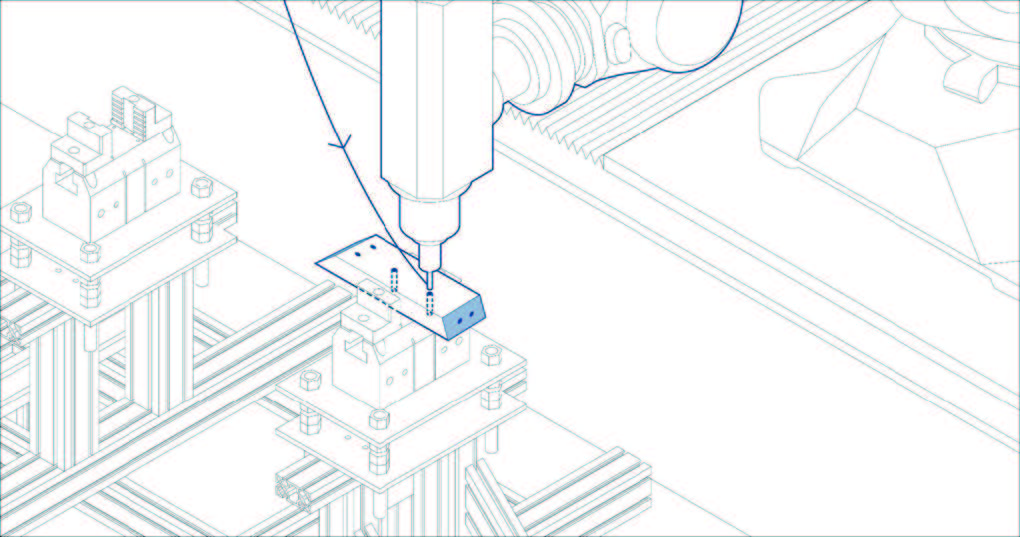
Step 03.
BOLT HOLE DRILLING
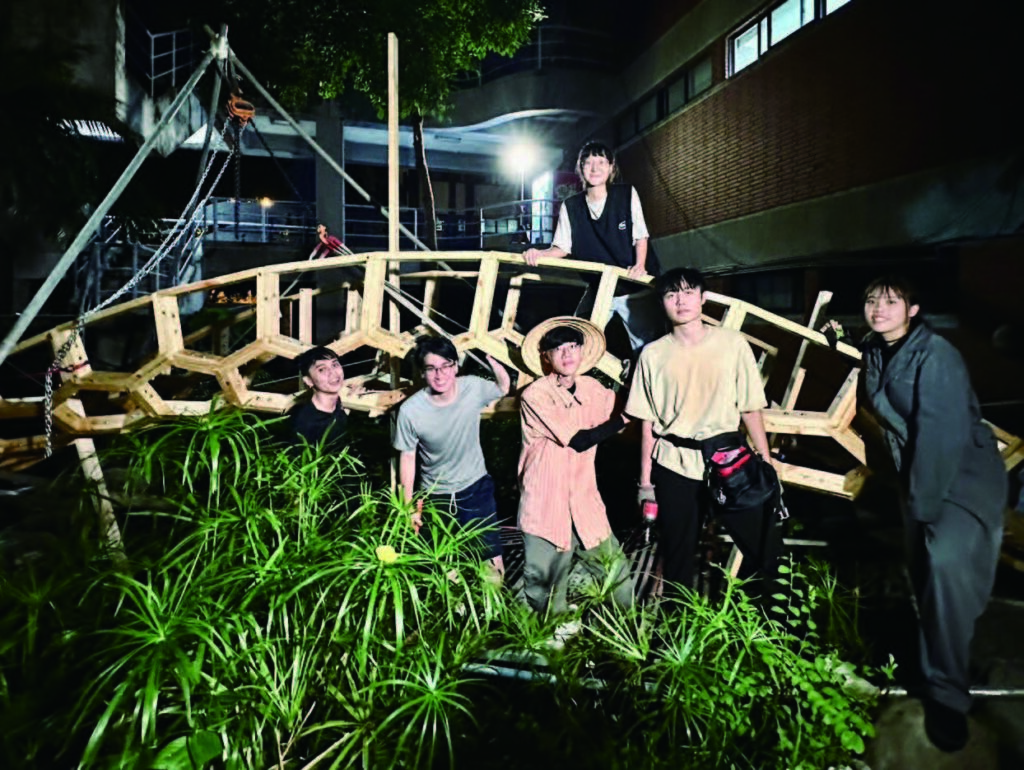
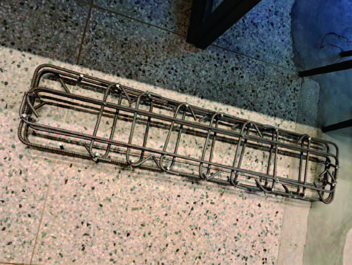
Construction
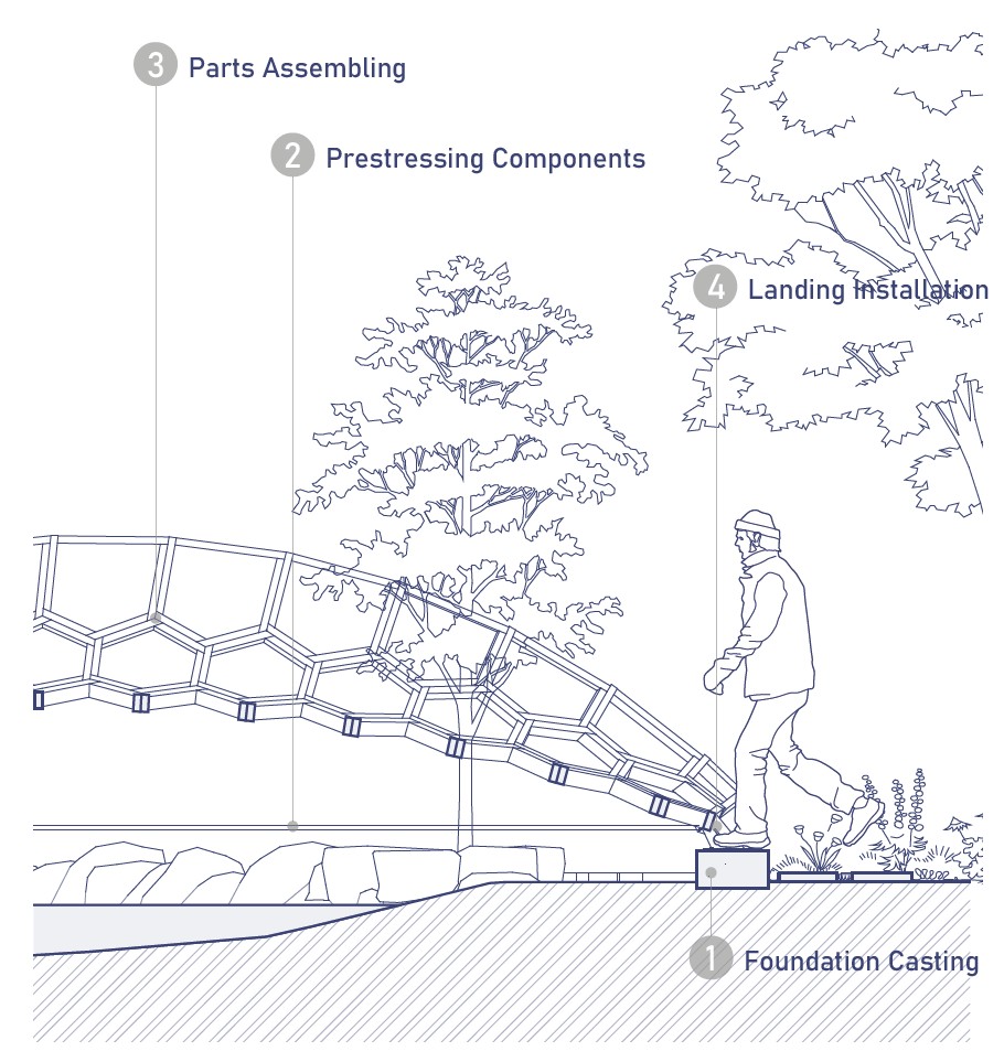
1
Foundation Casting
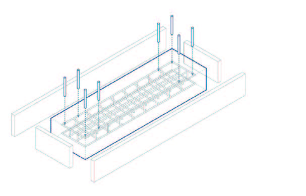
To withstand approximately 200 kilograms of its own weight and the expected live load it will bear
2
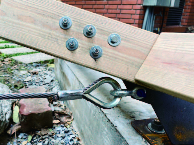
Prestressing Components
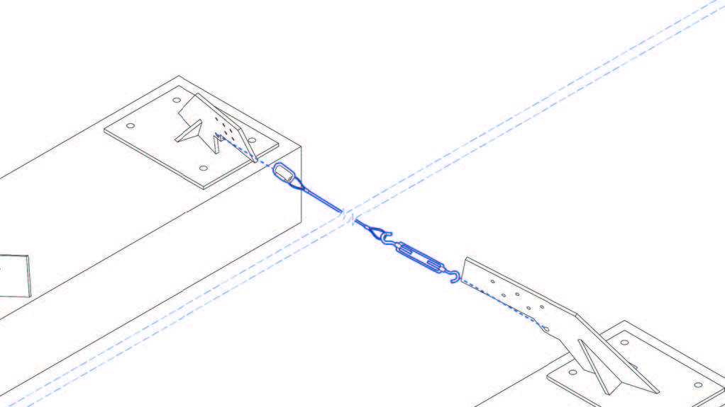
Using the tensile strength of steel cables to assist the foundation in resisting outward forces.
3
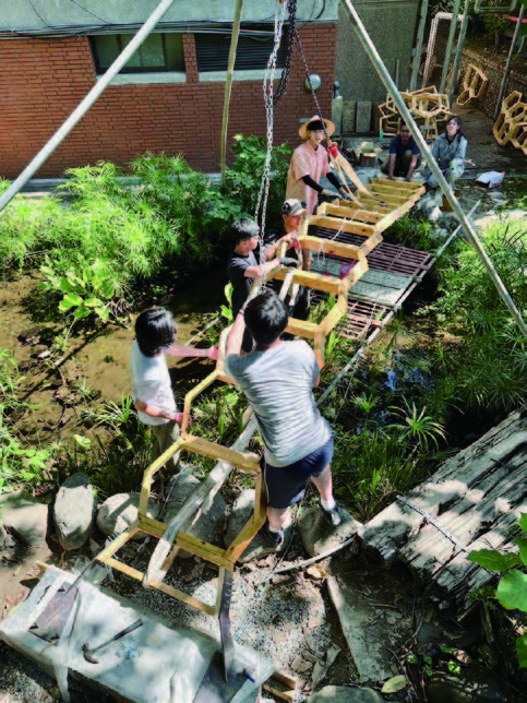
Parts Assembling
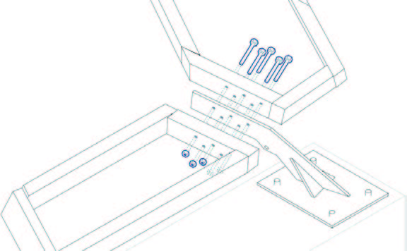
The construction sequence is influenced by the structural behavior, which also determines the locations where errors are absorbed
4
Landing Installation
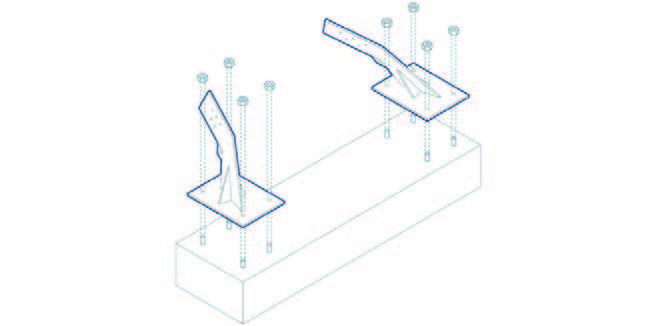
Transferring the bridge’s load to the foundation while accommodating construction errors.
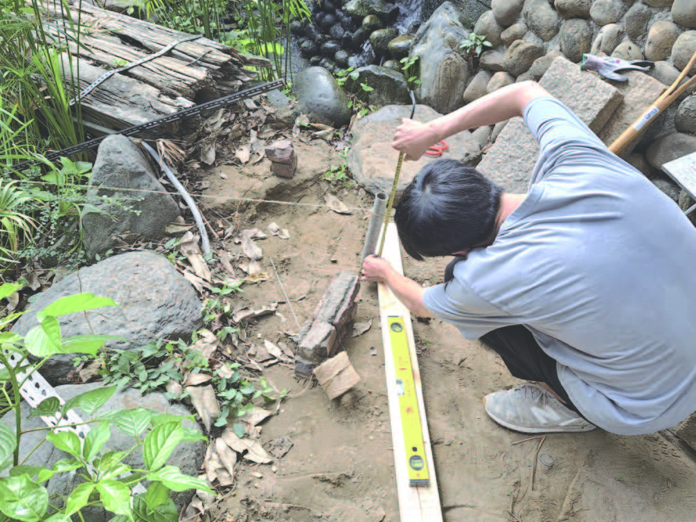
Construction
setting out
Concrete formwork

Cable installation
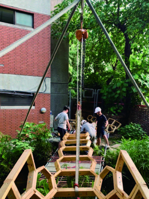
On-site assembly
Reinforcement
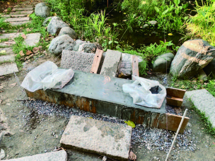
Foundation casting
Cable installation
On-site assembly